
Objective and Significance
Tensile strength is the maximum stress that a material can withstand while being stretched or pulled before breaking. The ultimate tensile strength is usually found by performing a tensile test and recording the engineering stress versus strain. The highest point of the stress–strain curve is the ultimate tensile strength and has units of stress.
Tensile strengths are rarely of any consequence in the design of ductile members, but they are important with brittle members. They are tabulated for common materials such as alloys, composite materials, ceramics, plastics, and wood. In brittle materials the ultimate tensile strength is close to the yield point, whereas in ductile materials the ultimate tensile strength can be higher.

Aim
To Determine Tensile Strength of the Reinforcing Bar by Universal Testing Machine (UTM)
Apparatus
Universal Testing Machine
UTM has two main units, one is the loading unit and the other is the control panel. The loading unit applies tension to the specimen at the desired load and the control panel gives the readings and manages all the data input.
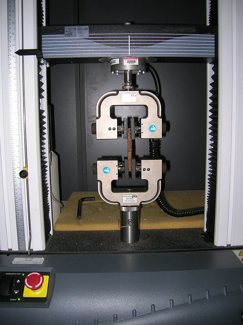
Punching Tools
Used to Mark Gauge Length of Specimen
Vernier Calipers
Used to measure Elongation length of the steel.
Extensometer
Used to measure deformation in the specimen
Procedure
- The specimen is then placed on the testing machine by operating the handle in such a way that the specimen firmly fits at the base.
- The right valve is kept in an open position while the left valve is kept in a closed position.
- The pointer is adjusted to zero utilizing the adjusting knobs.
- The specimen is gripped firmly and after the placing of the specimen, the jaws are locked.
- The extensometer is then fixed on the specimen and the reading is set to zero.
- The load is then applied using the right valve.
- The release of the loaded specimen is done using the left valve.
- The loading rate is increased gradually until the pointer moves backward and the specimen finally breaks.
- The maximum load reached during the test is known as the ultimate load and the load at the instant of breaking is known as the breaking load.
- The change in length can be obtained from the extensometer reading.
- Stress at different values of strain is computed from the following formula and the graph is plotted.
Stress = Load ÷ AreaResults and Calculations
Useful Formulae
- Modulus of Elasticity, E = Stress/Strain [This is calculated within the elastic limit. The slope of the stress-strain curve provides the modulus of elasticity]
- Yield Stress = Load at yield Point/Original C/s Area
- Ultimate Stress = Ultimate Load/Original C/s Area
- Nominal Breaking Stress = Breaking Load/Original C/s Area
- Actual Breaking Stress = Breaking load/Neck Area
- Percentage elongation = (Change in length/Original Length) × 100
- Percentage reduction in the area = ((Original Area − Neck Area)/Original Area) × 100