
J-Ring Test
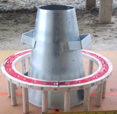
It denotes passing ability of the self compacting concrete. This test method covers determination of the passing ability of self-consolidating concrete by using the J-Ring in combination with a slump cone mold. The test method is limited to concrete with maximum size of aggregate of 25 mm. This test method provides a procedure to determine the passing ability of self consolidating concrete mixtures. The difference between the slump flow and J-Ring flow is an indication of the passing ability of the concrete. A difference less than 1 in (25 mm) indicates good passing ability and a difference greater than 2 in (50 mm) indicates poor passing ability. The orientation of the slump cone for the J-Ring test and for the slump flow test without the J-Ring shall be the same.

Apparatus
J-Ring – The apparatus shall consist of a steel ring measuring 12 in (300 mm) in diameter at the center of the ring and 1 in (25 mm) in thickness, and sixteen ⅝ in (16 mm) diameter smooth steel rods spaced evenly around the ring measuring 4 in (100 mm) in length.
Mold – The mold (slump cone) used in this test method.
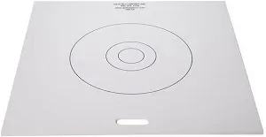
Base Plate – A nonabsorbent, rigid plate having a diameter of at least 36 in (915 mm).
Strike Off Bar
Measuring Device – A ruler, metal roll-up measuring tape, or similar rigid or semi-rigid length measuring instrument marked in increments of ¼ in (5 mm) or less.
Procedure
- Perform the test on a flat, level, and nonabsorbent base plate. Position and shim the base plate so that it is fully supported and level. Pre-moisten the base plate with a damp towel, rag, or sponge. Rest the J-Ring at the center of the base plate.
- Filling Procedure B (Inverted Mold) – Dampen the mold, and place it on the base plate with the smaller opening facing down and concentric with the J-Ring. Support the mold and fill the mold in one lift. Heap the concrete above the top of the mold.
- Strike off the surface of the concrete level with the top of the mold by a sawing motion of the strike off bar. Remove concrete from the area surrounding the mold to preclude interference with the movement of the flowing concrete. Raise the mold a distance of 9 ± 3 in (230 ± 75 mm) in 3 ± 1 s by a steady vertical lift with no lateral or torsional motion. Complete the entire procedure from start of the filling through removal of the mold without interruption within an elapsed time of 2½ min.
- Wait for the concrete to stop flowing and then measure the largest diameter (d1) of the resulting circular flow of concrete. When a halo is observed in the resulting circular flow of concrete, it shall be included as part of the diameter of the concrete. Measure a second diameter (d2) of the circular flow at approximately perpendicular to the first measured diameter (d1). Measure the diameters to the nearest ¼ in (5 mm).
- Conduct a slump flow test without the J-Ring. Use the same filling procedure as used with the J-Ring. Complete the tests with and without the J-Ring within 6 min.
Calculations
- Calculate J-Ring flow according to the following equation:
J-Ring flow = (d1 +d2)/2 - Calculate the slump flow according to the following equation:
Slump flow = (d1 +d2)/2 - Calculate the difference between slump flow and J-Ring flow to the nearest ½ in (10 mm). This number represents the passing ability of the concrete.